
If you have been reading my blog or watching my YouTube channel you would know that I do mainly large format photography. I often take my own self portrait for using my pneumatic cable release that has a long cable and air bulb release.
However I have always been thinking on how to make a more modern kind of remote cable release and hence this project.
Research
I search the internet for ideas on how other have make their own cable release and see what are the different components they have used. Primarily they will make use of
- a microcontroller
- a linear actuator that will press the traditional cable release
- a trigger device to send signal to the microcontroller
So I decide to add my own flavor to my own remote cable release.
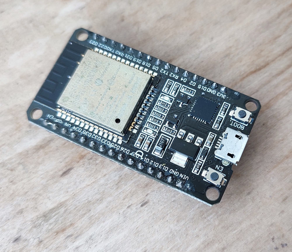
For the microcontroller I decided to use a Esp32 microcontroller development board. The ESP32 chip has been popular with iOT devices. It has built-in Wi-Fi and Bluetooth capabilities. However for this project I will use the Bluetooth function to do the communication.
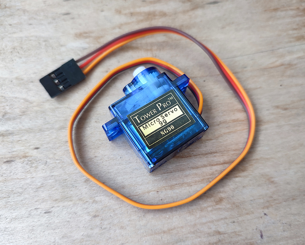
For the linear actuator I found a 3D design on the Internet you may use of a small Servo motor (SG90 mini servo motor) and a 3D printed rack and pinion. The linear rack will push a plunger of the mechanical cable release which in turn will trip the shutter on the lens/camera.
For the project case I modified it out of a project case template that I downloaded from this Andreas Spiess channel. I customize it to my needs : mainly to make some holes for the cable release , USB port of the ESP32 board, the mounting holes for the servo motor and the esp32 board. Both STL files are available on my github .
Design
So here is the simple electronic design diagram of my remote cable release.
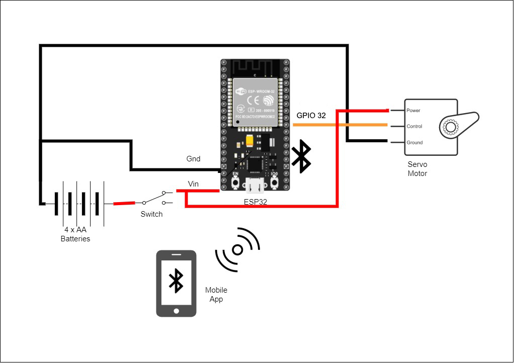
The connections are quite simple, we have the battery power
(4x AA batteries) to power both the servo motor and the esp32 board. A power switch will be used to turn on and off the circuit. The circuit should be off when not in use as the servo motor will also draw current when not moving.
The servo motor signal will be coming from a GPIO ouput pin from the esp32 board. The signal will have the motor rotate by a certain angle and in which direction. This will be translated into a linear movement using the rack and pinion.
Assembly
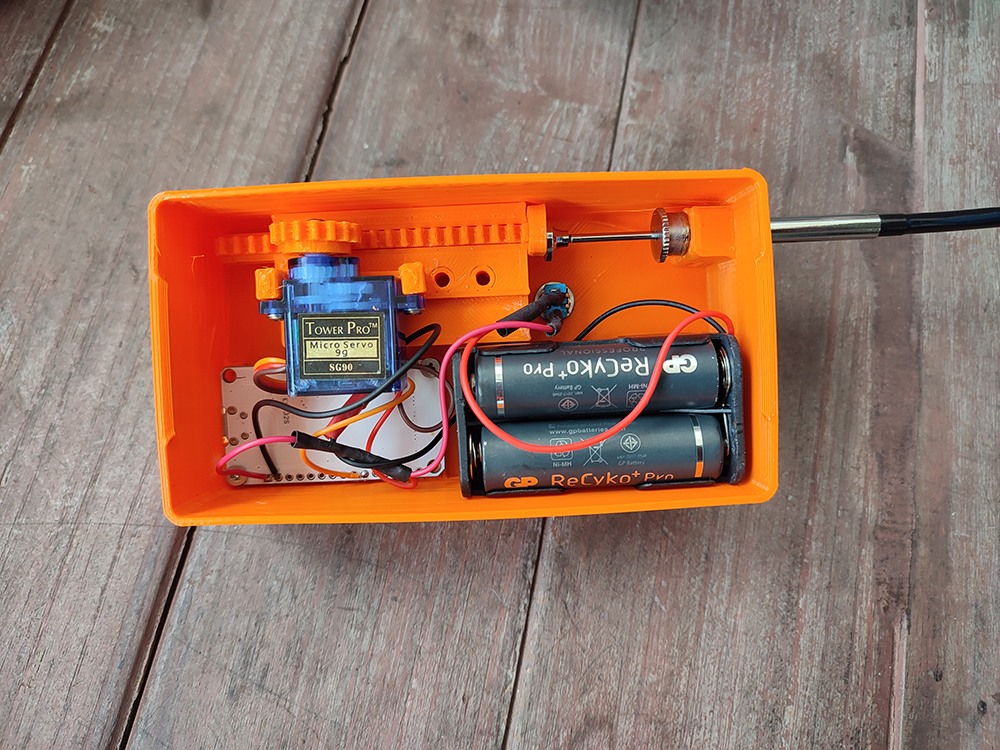
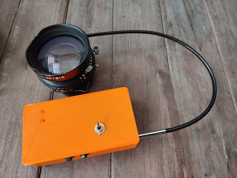
Once the parts are gathered, soldered and 3D printed, they are assembled together. The mechanical cable release is inserted into the case first otherwise it will be blocked by the other parts.
I designed an mobile app that uses Bluetooth to communicate with the main unit. On the mobile app, there are four functions
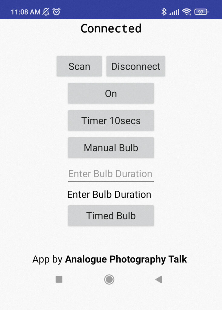
- On mode – immediate trigger of the cable release (shutter speed set on lens/camera)
- Timer 10 secs Delay mode , the shutter will be trigger after 10 secs. This is best for self portrait shots.
- Manual Bulb mode – at the first press, the shutter will be triggered and release at the second press (shutter speed set to B mode)
- Time Bulb mode – set the duration in seconds and when the button is pressed, the shutter will be automatically triggered and released at the end of the time. (shutter speed set to B mode)
Coding
I use the Arduino platform to create the esp32 program and the MIT App Inventor to create the mobile app. As I am no professional programmer, I’m sure that they are a lot of improvements that can be made. I will share both codes on my github as open source for anyone who is interested to use or improve .
Conclusion
This is an interesting project that that allows me to develop my electronics and coding skills. There is a few issues that can be further improved on :
- make the unit even smaller
- have a way to mount this on a camera hotshoe/cold shoe
- a stronger servo motor
- a better rechargeable battery source
- a digital output to trigger some digital cameras