Category Archives: DIY Projects

How to Create Your Own Instant Film

A decade ago, I stumbled upon a page where someone detailed their process for crafting their own instant film, something similar to Polaroid Type55 or the New55. At that time, the instructions seemed too complex for me to tackle, and I never ventured into the world of instant film creation.

Fast forward ten years, and I’m now prepared to give it a shot. The reason? There’s now a lot more information and instructions shared by others who have explored this fascinating process.

How to make your own instant film video

With that in mind, I decided to create a video and write an article to guide anyone interested in crafting their own instant film and taking the plunge into this venture. So, here’s your step-by-step guide on how to make your own instant fil

Monobath paste

Making the thickening agent

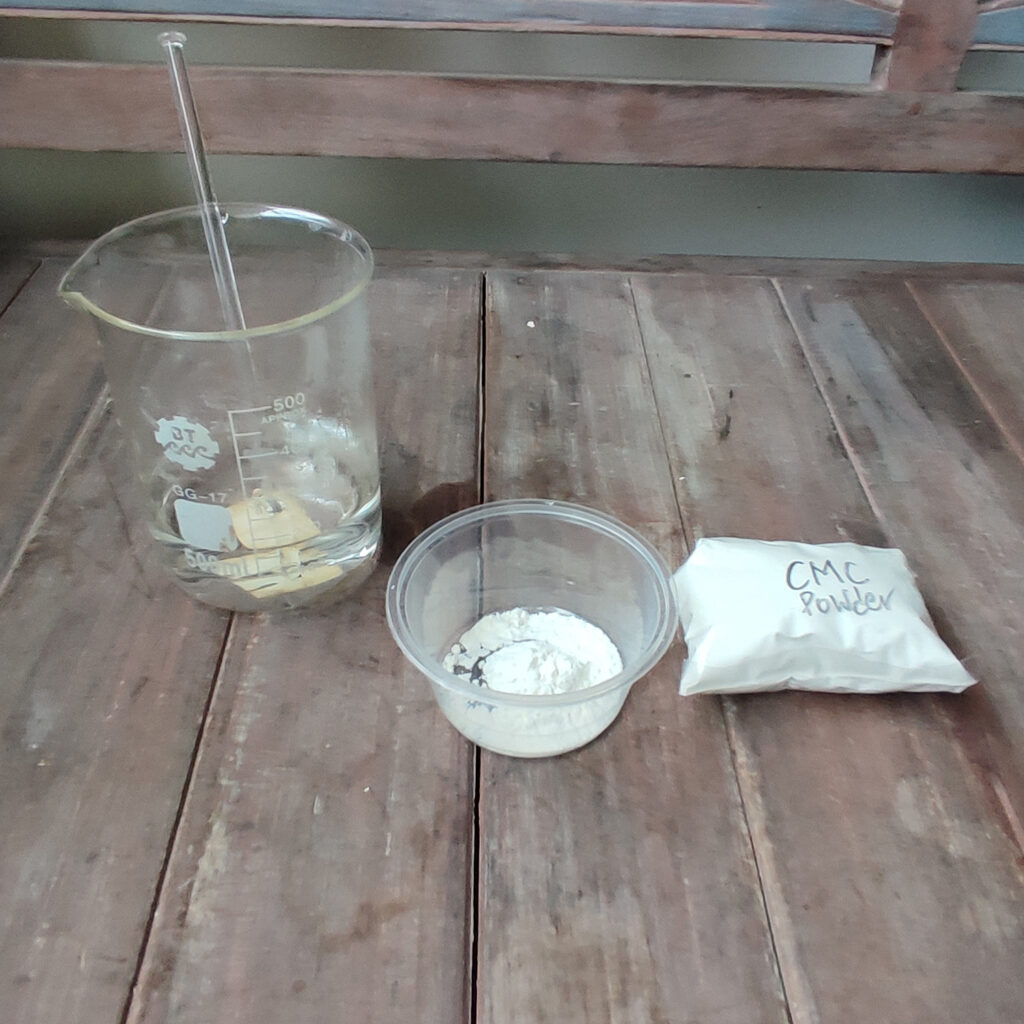
a. Thickening Agent: Combine 5g of Carboxymethyl cellulose (CMC) powder with 100ml of water. Heat the water to approximately 70°C, then gradually add the CMC powder while stirring continuously. Keep stirring until you achieve a uniform, viscous paste. Cover the mixture and let it sit overnight or a few days to get rid of the air bubbles and to smoothen the paste.

b. 15% Sodium Hydroxide Solution: Mix 7.5 grams of sodium hydroxide in 50ml of water. Caution: Wear safety glasses and gloves as this mixture may splatter and generate heat. Let it dissolve and measure the pH. You may need add sodium hydroxide or water until you reach a pH level of 12

c. Monobath:

Making the Monobath
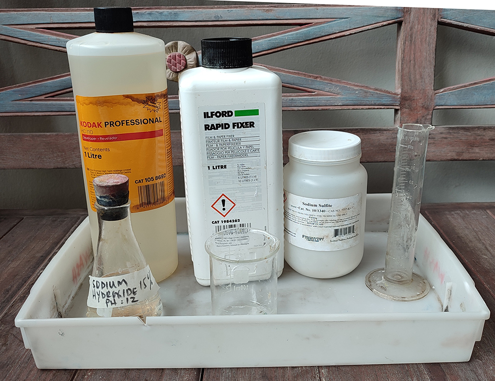
  1. Combine 8ml of Kodak HC110 (using the newer, less viscous HC110).
  2. Add 1ml of Ilford Rapid fixer.
  3. Mix in 4ml of sodium hydroxide from step (b)
  4. Add 0.5 grams of sodium sulfate.
  5. Next, add 10ml of the thickening agent prepared in step (a) to this mixture. Stir and blend thoroughly. The pH of this solution should be around pH 9. Cover it and let it sit for a few hours or even a day until the paste becomes smooth and well-incorporated.

2 Creating the Pod

Making the chemical pod using freezer paper

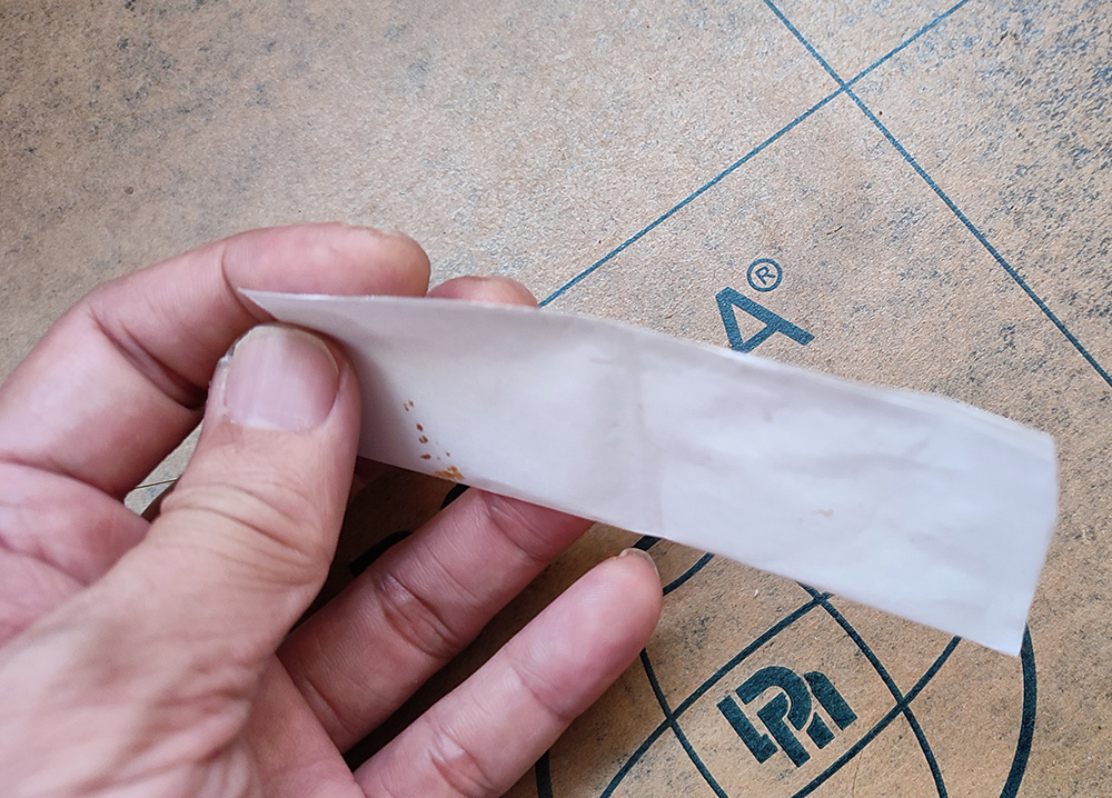
a. Cutting the Freezer Paper: Take a piece of freezer paper measuring 12×7 cm. Fold it in half along the long side, with the plastic layer on the inside.

b. Sealing the Long Side: Seal the long side using an appropriate heat sealer. I used setting no 3.5. The goal is to create a strong seal that won’t leak but is still weak enough for the rollers of the Polaroid 545=to break.

c. Dividing the Pod: Increase the heat sealer setting (to 4.5 in my case) and seal along the center of the short side. This effectively divides the pod into two pockets.

d. Filling the Pod: Use a syringe to inject 1ml of the viscous monobath into one pocket and seal the short ends. Repeat the process for the other pocket. Both seals should be sealed using the higher setting.

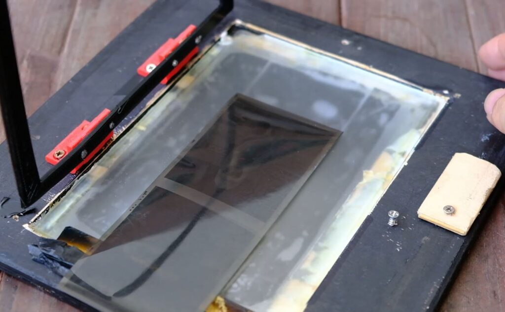
3 Receiver Positive Sheet:

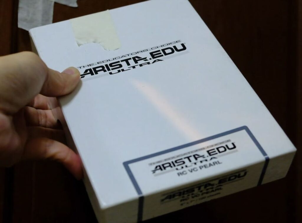
a. Preparing the Sheet: Take expired Ilford RC 5×7 paper and fix it in rapid fixer (1+9) for 2 minutes without exposing it. Wash and dry it, then cut it to a width of 4 inches, leaving the length uncut.

b.Creating Space: Apply two narrow strips of masking tape along the two long sides. This creates a gap between the sheet and the negative, allowing a layer of monobath paste to be spread between the two surfaces.

Tape 2 narrow strips of masking tape to act as spacers for the monobath paste to flow


5 Using Foma RC Paper as the Photo Negative:

Preparing the Negative:
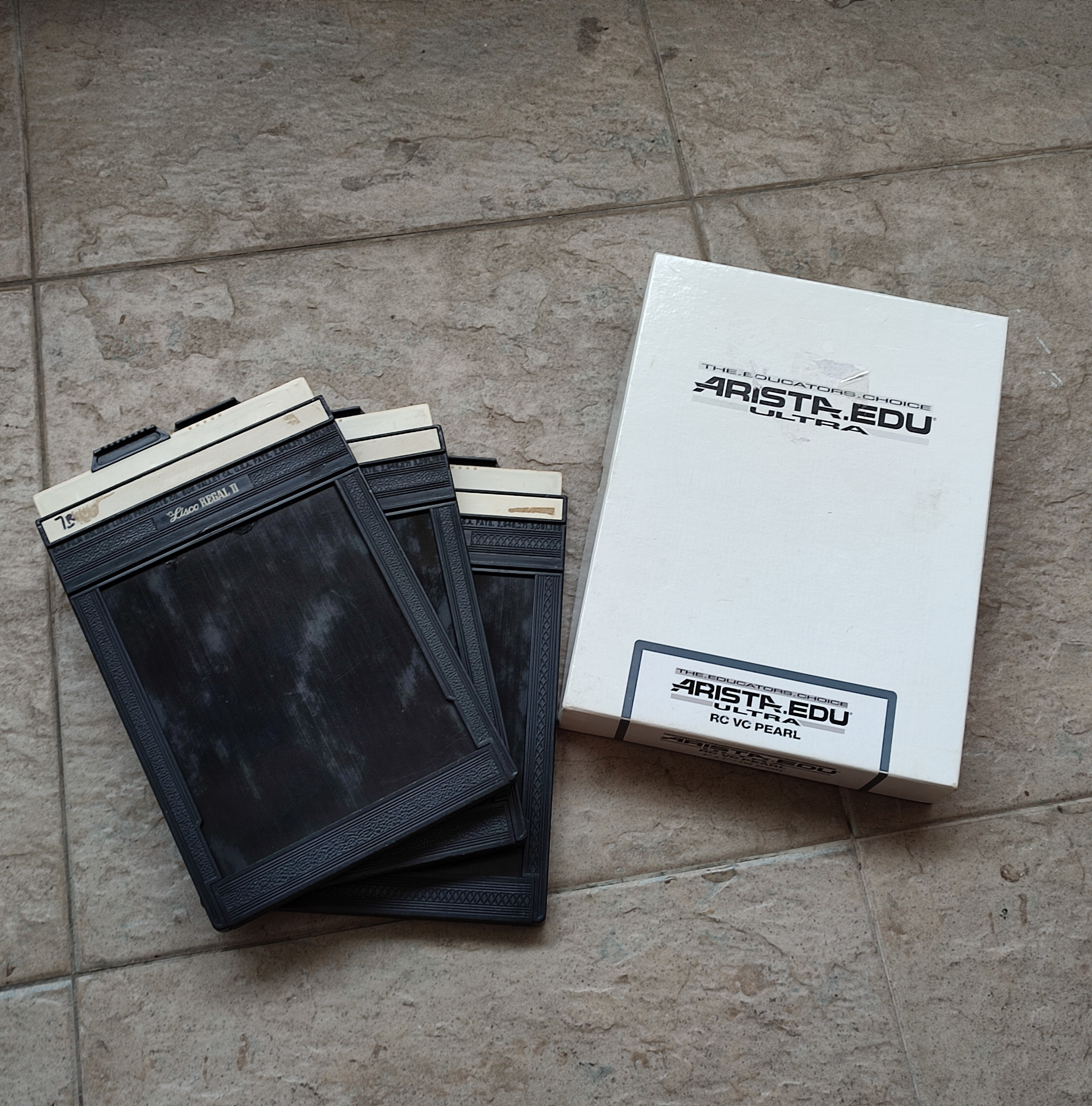
i. Cut the Foma RC paper down to 4×5 size and load it into the 4×5 film folder.
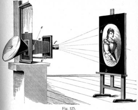
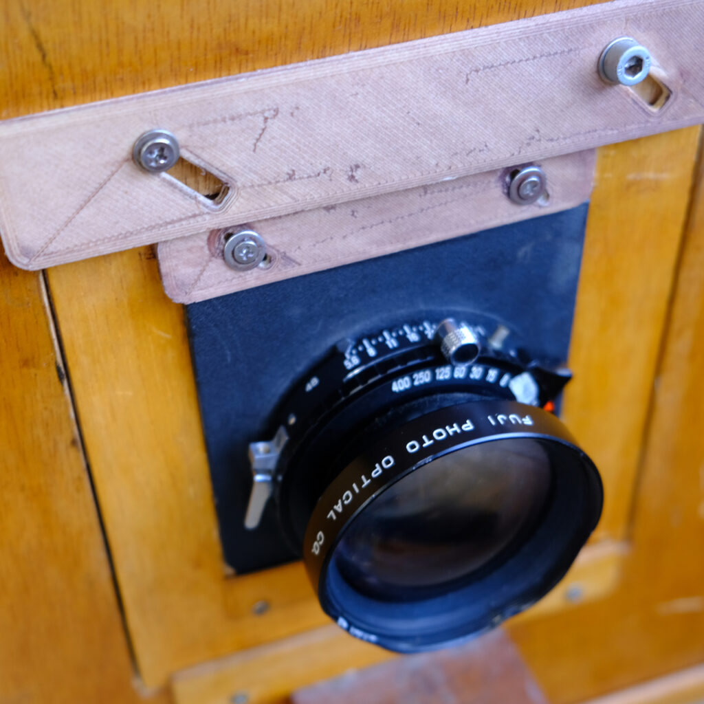
ii. Use a 4×5 large format camera to expose this photo paper negative (ISO 6).
iii. Since photo paper is used as the negative, final assembly can be done under red safe light conditions. If film is used as the negative, it must be assembled in total darkness.
iv. Place the exposed photo paper negative (emulsion facing down) on top of the positive paper at the pod to make it stick to the double-sided tape

Cut down 5×7 photo paper in the dark to 4×5 and load into the sheet holders

5 Assembling the Pod:

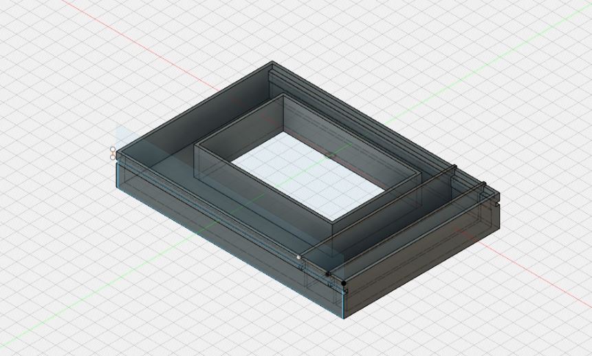
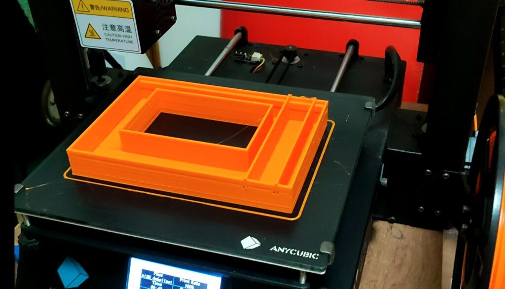
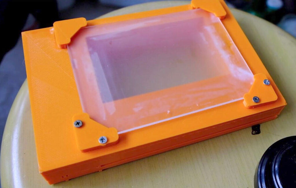
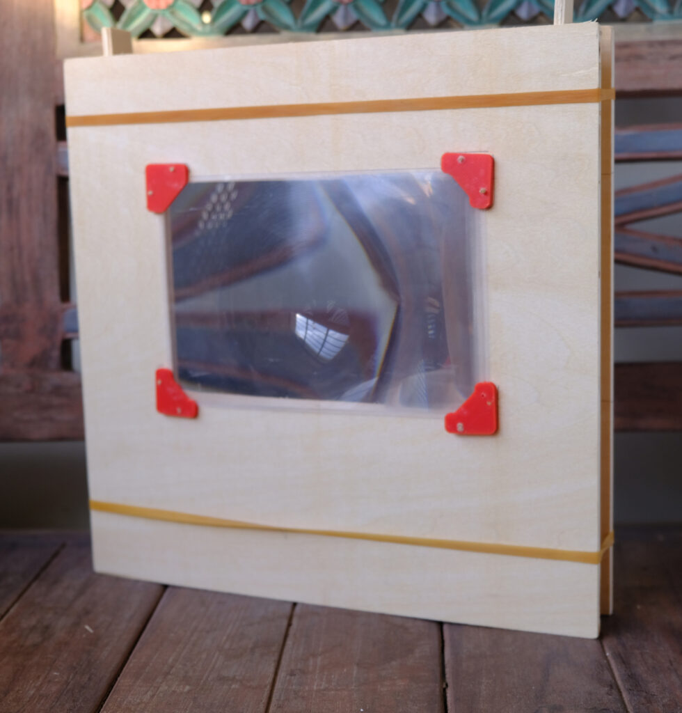
Creating a Rig: To simplify the assembly process, create a rig to help in aligning the pieces

Assembly Rig

i. Place the fixed photo paper with the emulsion side facing up.
ii. Securely tape the pod onto this paper.
iii. Apply a piece of narrow double-sided tape on the top side of the pod. This will allow you to attach the negative sheet on top of the pod, ensuring alignment between the negative and positive sheets.

6 Processing:

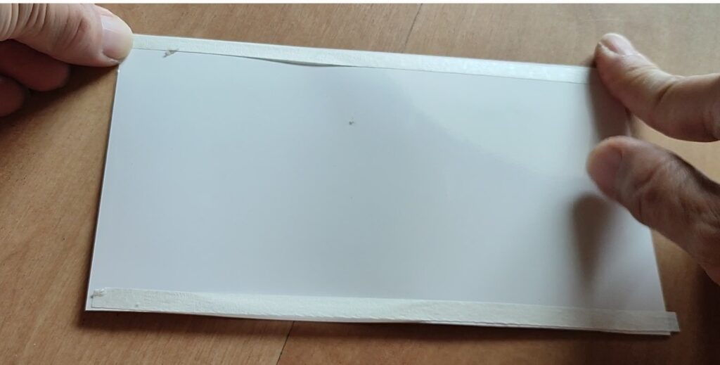
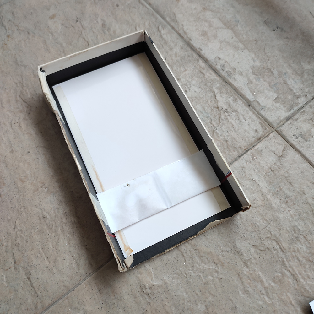
i. Use a piece of black paper to craft a black envelope that encloses the assembly. ( I used white paper in the video demo)

Polaroid 545 holder


ii. Load the entire assembly into the Polaroid 545 holder and slowly and firmly pull it through the rollers.
iii. If all goes well, the pod will break and spread the monobath paste between the negative and positive sheets.
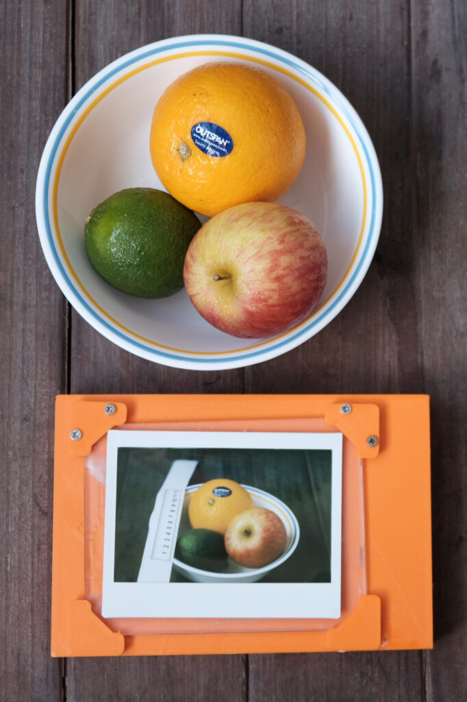
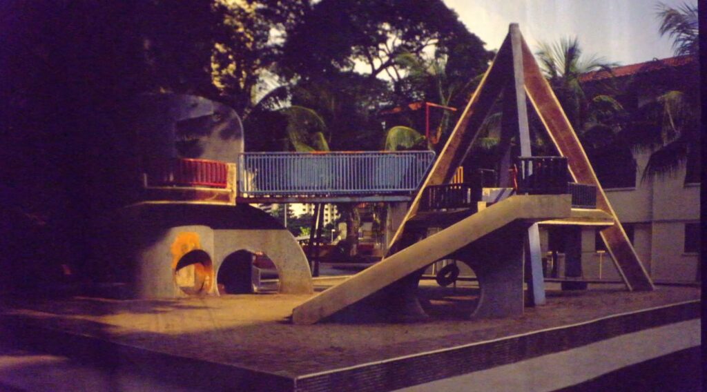
iv. After 5 minutes, remove it from the black envelope and carefully peel it apart to reveal a positive image and a negative.


v. Finally, fix the negative paper with some rapid fixer to stabilize it. For the positive sheet, a simple wash with water to remove the paste.

7 Conclusion

This isn’t instant film in the commerical product sense since you need to shoot the negative separately and manually assemble it in the dark. However, this concept provides insight into how diffusion transfer reversal works, opening the door for further experimentation. For now, I’ll conclude here, but if I explore different papers or develop a more ready-to-shoot package like Polaroid Type 555 or New 55, I’ll provide updates.

DIY Remote Mechanical Cable Release

If you have been reading my blog or watching my YouTube channel you would know that I do mainly large format photography. I often take my own self portrait for using my pneumatic cable release that has a long cable and air bulb release.

However I have always been thinking on how to make a more modern kind of remote cable release and hence this project.

Research

I search the internet for ideas on how other have make their own cable release and see what are the different components they have used. Primarily they will make use of

  1. a microcontroller
  2. a linear actuator that will press the traditional cable release
  3. a trigger device to send signal to the microcontroller

So I decide to add my own flavor to my own remote cable release.

ESP32 development board

For the microcontroller I decided to use a Esp32 microcontroller development board. The ESP32 chip has been popular with iOT devices. It has built-in Wi-Fi and Bluetooth capabilities. However for this project I will use the Bluetooth function to do the communication.

SG90 Micro Servo motor

For the linear actuator I found a 3D design on the Internet you may use of a small Servo motor (SG90 mini servo motor) and a 3D printed rack and pinion.  The linear rack will push a plunger of the mechanical cable release which in turn will trip the shutter on the lens/camera.

For the project case I modified it out of a project case template that I downloaded from this Andreas Spiess channel. I customize it to my needs : mainly to make some holes for the cable release , USB port of the ESP32 board, the mounting holes for the servo motor and the esp32 board. Both STL files are available on my github .

Design

So here is the simple electronic design diagram of my remote cable release.

The connections are quite simple, we have the battery power
(4x AA batteries) to power both the servo motor and the esp32 board. A power switch will be used to turn on and off the circuit. The circuit should be off when not in use as the servo motor will also draw current when not moving.

The servo motor signal will be coming from a GPIO ouput pin from the esp32 board. The signal will have the motor rotate by a certain angle and in which direction. This will be translated into a linear movement using the rack and pinion.

Assembly

Once the parts are gathered, soldered and 3D printed, they are assembled together. The mechanical cable release is inserted into the case first otherwise it will be blocked by the other parts.

Remote Unit connected to a large format lens

I designed an mobile app that uses Bluetooth to communicate with the main unit. On the mobile app, there are four functions

  1. On mode – immediate trigger of the cable release (shutter speed set on lens/camera)
  2. Timer 10 secs Delay mode , the shutter will be trigger after 10 secs. This is best for self portrait shots.
  3. Manual Bulb mode – at the first press, the shutter will be triggered and release at the second press (shutter speed set to B mode)
  4. Time Bulb mode – set the duration in seconds and when the button is pressed, the shutter will be automatically triggered and released at the end of the time. (shutter speed set to B mode)

Coding

I use the Arduino platform to create the esp32 program and the MIT App Inventor to create the mobile app. As I am no professional programmer, I’m sure that they are a lot of improvements that can be made. I will share both codes on my github as open source for anyone who is interested to use or improve .

Conclusion

This is an interesting project that that allows me to develop my electronics and coding skills. There is a few issues that can be further improved on :

  1. make the unit even smaller
  2. have a way to mount this on a camera hotshoe/cold shoe
  3. a stronger servo motor
  4. a better rechargeable battery source
  5. a digital output to trigger some digital cameras

How I 3D printed a ground glass back for use with my Lomography 4×5 Instant Back

In one of my recent videos I share how I shot with the 4×5 instant back (Lomograflok ) from Lomography. In that video I shot with my Chamonix 4×5 camera and I mentioned that we need to use a spacer every time we compose a shot.

That is to take into account of the different film plane on this back. The Instax Wide film plane is further away by 19.4mm from the usual sheet film plane. Another point I mentioned is that if I were to mount this back on the camera, I would need to remove the ground glass frame. The Chamonix ground glass frame is easy to put back ( one hand to slide the frame in)but difficult to remove ( you need 2 hands to lift out the 2 spring arms) and that is kind of troublesome if you have to do that for every shot.

So I decided to 3D printed a ground glass frame that already has the spacer built in and it’s also much easier to remove and put back. The new ground glass frame that I 3D printed is very similar in size to the spacer that came with the back. The only difference is the height which is about four mm higher to take into into account where the ground glass should be. The other thing I added was the grooves along the long sides so that it can be locked down. In contrast, there is no groove on the original spacer because will be held in place when you insert it into the groundglass frame

3D Design in Fusion 360

The 3D design is done in Fusion 360, nothing too complicated as the shape is quite regular. It is a matter of measuring the original spacer and transferring the measurements into the design. One of the thing is I nearly missed out are the 2 raised bars on the right side of the frame. These are used to align the entire frame on the camera back to prevent it from being inserted too much or too little.

I 3D printed it using my Anycubic Mega S printer with the following specs (for reference):

Layer : 0.3mm
Infill density : 20%
Extruder temp : 230C
Support : Everywhere
Time Taken : 5hrs

Printing on my AnyCubic Mega S 3D printer

The STL files can be downloaded here ( DO note this is a Work in Progress project)

Ground Glass

Acrylic ground glass

Instead of making my own ground glass, I opted for a piece of 3mm acrylic that is frosted on one side. I have a piece lying around from my Afghan Box cameras build so I decided to use it. There are also four corners that I used to hold the ground glass in place. The 2 bottom pieces are glued to the main body using superglue while the other 2 are secured with screws. This will make it easier to swap ground glass in the future by unscrewing the top 2 pieces.

Test shoot

So what was left is to do a test shoot to make sure the ground glass image plane is the same as the Instax Wide back film plane. I chose a still life setup and focused on the label on the orange. The results shown the there is no shift in focus switching from ground glass to instant back.

Resultss


Improvements

The radial locks to catch the groove are not well aligned. Although the 3D frame is still held in place, it is something to look into.

Conclusion

While the 3D printed back is not perfect, it certainly make using the instant back easily with my Chamonix camera. Other 4×5 cameras may not require this if the back can be slotted under the ground glass.

DIY Photo Enlarger from an Afghan Box Camera

In my previous post, I shared how I converted my Afghan Box Camera into a slide projector. The principle of the slide projector involves putting a light source at the back whose light passes through some condenser lens. The light then goes through the slide and finally pass the projector lens and be projected big on the the projector screen.

Typical enlarger design Used under CC license

I thought that would be about the same principle as a photo enlarger in the dark room. In the enlarger we have also the light pass through some condenser lens (depending on the design) and it will pass through the negative, go through the lens and it will be projected big on the photo paper so I thought maybe I would try to use my Afghan Box Camera again to convert it into photo enlarger  in this case it will be horizontal enlarger where I will project the image horizontally onto the wall surface.

Negative Carrier

Negative Carrier

I decided to use my photo paper holder inside the Afghan Box Camera for this conversion. I taped up a 6x7cm window using some black PVC tape. If this is to be a more permanent setup, I would make a proper negative carrier for now. For now, this will do and I used some small pieces of masking tape to secure the 6×7 negative flat against the glass. To focus I would move the focusing rods per the usual way when using the Afghan Box Camera which move the negative towards or away from the lens.

Light Source

Unlike a light source for a slide projector, the enlargement is smaller so light source for this enlarger can be relatively less powerful. So I use a simple 11W warm color LED bulb. As I do not have a timer, I simply use the on/off switch for the bulb during printing to control the exposure time.

Lens

I do not have a dedicated enlarger lens so I use my trusty Fujinon 210mm lens as the enlarging lens. For a safe filter, I dug out an old Cokin red filter and a Cokin filter holder. I would just slip the filter and holder over the lens if I need to block the light from reaching the photo paper.

Paper


Arista Edu 5×7 inches Resin Coated paper

I use the Arista Edu 5×7 inches Resin Coated paper. Being a variable contrast paper, I could use the Ilford Multigrade Contrast filters to control the contrast of the print. Again, this is done simply by taping the filter on the rear element of the lens during printing.

Results

The results shown that the box camera can be easily turned into a photo enlarger by making a few changes to it

  • Add in a light source
  • Replace/convert the photo paper holder with/into a negative holder
  • Add in safelight filter and contrast filter

Improvements

Nevertheless,  a few improvements can be made

  • Better way of holding the paper on the wall instead of just using masking tape.
  • Some method to confirm the squareness of the enlarger to the photo paper
  • Better way to hold the safe filter and contrast filters

Conclusion

Vintage Solar based Horizontal Enlarger

Horizontal enlargers have been around for a long while and box camera users can consider turning their box camera int0 an photo enlarger if they need a quick print from a negative.

How to Get Large Format Film Look with a Mobile Phone Camera

Remember my previous post where I turned my Afghan Box Camera into a 4×5 slide projector? Today I have another idea around the Afghan Box Camera – that is to make use of my humble mobile phone camera to create a large format look by making use of the box camera and its lens.

This is much inspired by other fellow photographers who have designed similar stuff such as this by
Olexiy Shportun and another by Tim Hamilton. The main idea behind this is to make use of a digital camera to take a photo of the projected image made by the large format lens.

Design

In my design, I decided to make use of a mobile phone camera rather than a DSLR or mirrorless camera. However how would I control the mobile phone camera if the phone is placed inside the box? Luckily there are various apps that will help us.

Remote Control

IP Webcam app

For my Android phone, I decided to go for the IP Webcam app for its versatile. It is free, can be used via Wi-Fi and easy to use. Hence by using this app, the mobile phone camera can be controlled and hence trigger off remotely.

After some testing, I realised that the phone camera cannot be too near the ground glass otherwise the phone camera will produce an image with a hot spot. The best position I found is to place the phone all the way to the back of the box camera. The ground glass image will only occupied about half of the camera phone photo framesize. This can be easily overcome via zooming in via the control interface or cropping during post processing.

Webcam Control Interface

The IP Webcam control interface is easy to use, I usually play with the following settings

  1. Zoom – to zoom on the ground glass image as mentioned above
  2. Exposure compensation – this settings can be adjusted from -12 to 12 steps (not sure how 1 step is equivalent to a photographic stop)
  3. Effects – like any phone digital camera filter , you can set it to Black & white, sepia , negative. My favorite is black & white simply to minic the usually monochrome photo we take with black & white photographic paper.
  4. White balance – for shooting in color, Daylight settings seems to boost up the colors saturation quite a bit.

Some Sample Photos

In conclusion, this method of hybrid shooting has potential to be explored further. My best use of such way of shooting was in an educational workshop during this pandemic time where safe distancing is encouraged so to be able to show what is happening on the ground glass remotely is particular useful.

Making a 4 x 5 slide projector

My build video on Youtube
4x5 slides on a light table

4×5 slides on a light table

I have been shooting 4 x 5 color transparencies or commonly known as color slide film for many years but the best that I could enjoy them was to put  them on the light table and  viewing them  through a loupe. Unlike my 35mm and 120 slides, I have never seen them projected big simply it is not easy to locate a 4×5 slide projector.

For the last few years, I tried searching online on how to do it yourself (DIY) and build a 4x 5 slide projector  but no one seems to have make them before.   There are commercially  produced 4×5 slide projectors although I never seen one in real life. I have not even seen them on the used market on eBay before but even if they are available they are going to cost a lot and even more to ship.

 It was only recently that I saw this YouTube video by DIY Perks on how he made a 4K LCD projector that triggered me to think about making a 4×5 projector again.  in this video he explained how he made use of the Fresnel lens instead of the conventional thick condenser lens.

Afghan Box Camera

With this new knowledge, I started to think how I can convert my Afghan box camera into a slide projector. For those who do not know the Afghan box camera, it is a camera and darkroom built into a single box. If you need more info on how to build one you can refer to this amazing ebook by Lucas Birke on his Afghan box camera project .

Light source

Philips 12B LED light bulb

Philips 12B LED light bulb

The most important part of the side projector is a powerful light source. The conventional projector will use powerful  but hot incandescent or halogen light bulb. However for this project I went to the store and find the highest wattage LED Bulb.  This turned out to be a 12 watts LED light bulb from Philips. It is also warm light which is what slides are usually projected with. It was said the slides usually come with a blue tint to balance out the warm light.

I wired with up with a socket (WARNING : live wire is involved. DO NOT do this yourself if you are not confident or trained. ) and attached it to the back of the box camera using 2 screws.

Fresnel lens

Fresnel lens sold as magnifying sheets

I went online and bought 2  magnifying reading  sheets  that are usually use for reading but I guess they would work for this purpose. On every sheet there will be one side that is make up of the Fresnel lens which is a series of concentric circles and the other side will be smooth so it is important the place that sheets in the right orientation.  The one nearest to the light bulb have the Fresnel lens facing away from it and the other piece will have the concentric circles facing the bulb. In this manner, the light from the bulb will be collimated By the first piece and converged by the second piece.

It is also important to find out the true focal length of the Fresnel lens. TheDIY perks video shows you how. My 2 lenses have focal length of 90mm.

Fresnel lens separated by a narrow strip of plywood

To mount  the lenses I just got two pieces of plywood with a window cut in the center and I  3D printed some corners to mount the lenses to the plywood. To attach the 2 Fresnel lens plywood in the Box camera I just   use 2 narrow strips of plywood and 2 elastic bands to act as a spacer between the 2 boards. The idea here is  to be able to convert this back to a box camera instead of turning it permanently into a slide projector.

Lenses


Fujinon 210mm lens

For lens I continue to use my Fujinon 210mm lens which is my
large format photography shooting lens . I find that it still do a decent job in projecting the image however I’m not sure sure if there is a difference in projection quality if I were to use a enlarger lens or projector lens.

Focusing

In order to focus the image on the screen I use the focusing rods that is already part of the box camera system. This box camera is designed to take 5×7 inches photo negative so I removed the existing ground glass and made a 4×5 slide mount to hold it to the holder and to block off excess light .

Testing

For testing I set up a piece of 5feet white fabric backdrop mounted across two light stands and was placed see about 3 meter from the slide projector in the darken room with all the lights off. Hooya! I was able to get a good image on the screen! I was certainly very impressed and I to be able to see my large format slides on such a big screen finally !

Conclusion

While this slide projector is not bright enough to be used in an auditorium, it is good enough for personal viewing of 4×5 slides at home. You will need a very dim room to enjoy the slides at a view distance of 3 metres. There are certainly room for improvements but that will be for another DIY made.

DIY Wet Plate Collodion Darkbox

For wet plate collodion process, the plate has to be developed before the collodion get dries up. Therefore an wet plate collodion darkbox is essential for outdoor shooting. There are many designs for a darkbox that can be found  online but  I opted for a briefcase design as you can see in the video below.

The dimensions of my darkbox when closed are 29″ x 22 ”  x 5.5″ making it a very compact size. It is constructed out of plywood and hardwood pieces without any fanciful woodworking joints. The wood pieces are simply joined together using screws.

Let me know if you have any questions.