Category Archives: Ultra Large Format

Building a ULF 16×20 camera with a massive aerial lens and cardboard

A few years ago I built a ultra large format camera that is 24 inches by 24 inches. While it was a pretty huge camera, it was a simple build it was just two square standards, one for the front and one from the back which were connected by a big bellow.

There was no support base or focusing rails and I just support the two standards by using two tripoda so it was not the most stable camera. After a while I dismantled the whole setup and recycled the wood and the bellows so I thought that would be the end of my Ultra Large Format (ULF) camera building adventures but who knows a while back, my friend passed me a big lens and it got me thinking of rebuilding a ultra large format camera again.

Lens

The lens compared to a Nikon film SLR

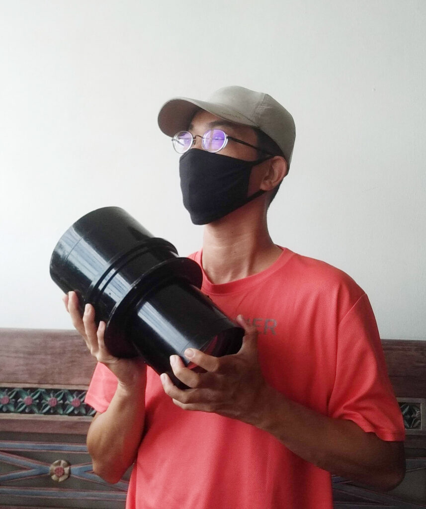
The story was that my friend came across a camera collector near a local market during one of his walks and spotted this big lens. Money changed hands and he bought over the lens.

After some research, I discovered that it is a aerial lens. It was used in aerial camera mounted on aircraft for surveillance photos probably during World War 2 or later. The lens weighs eight kilograms and the focal length is 36 inches and has the biggest aperture at f6.3. However no brand or maker’s mark can be found on it. it may be one of the few lenses that were made by different companies during the war.

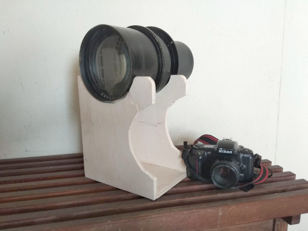
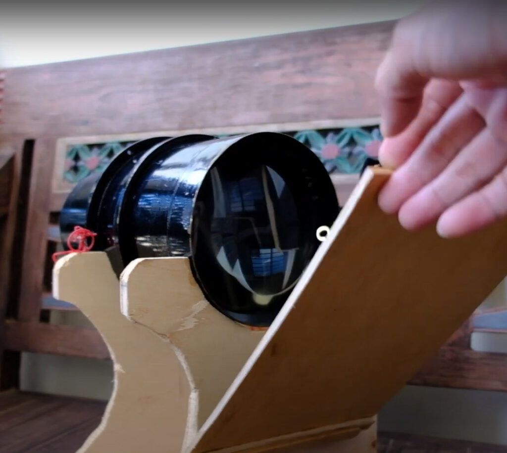
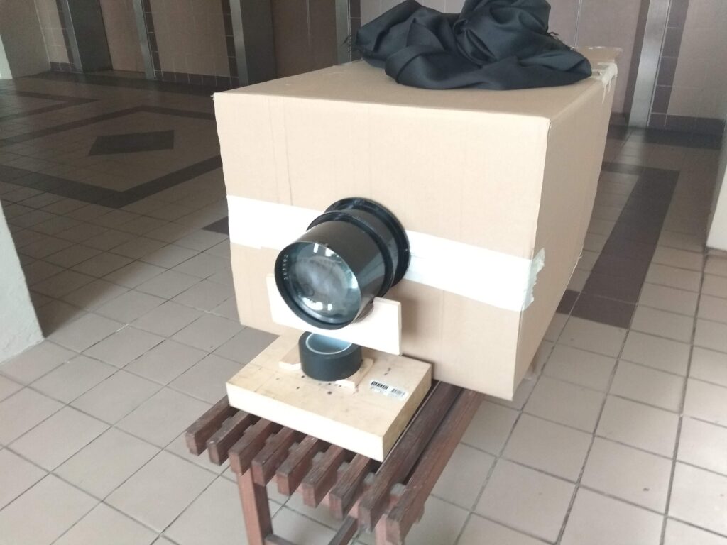
As the lens is so heavy so I built a wooden lens support for it. It is made with a few pieces of wood and cut some curves that will fit the front part of the lens. I also designed it so that there are two height adjustments as my camera design will be of a rectangular shape and there may be a need to mount the camera at different heights for landscape and portrait orientation.

Watch the video about the lens here :

Camera

As I do not have the space for for a ULF camera I decided to just make one from corrugated cardboard boxes. I opted for a sliding camera design but with a twist in the back design. It has 2 sleeves holes cut out at the sides so that I can put my hands inside to load the paper. The “dark slide” would be at the back of the camera covering up the ground glass when I need to load the photo paper and doing exposure. With no removable film holder, I would load the paper would by sticking it on the ground glass using magnets. I am not sure is this considered innovative but I must say I never come across similar design in other cameras.

Watch the video about the camera building here :

Shutter

Flap Shutter

While the camera has a working aperture, there is no shutter control for it. Initially I built a simple cardboard lens cap for it and use it to control the exposure. That is a ‘remove and place back’ the lens cap for exposure. This is a common method to control exposure in barrel lenses. However this method will not work if I were to take my own self portrait.

As the lens is so big (diameter ), it is hard to find a commercial shutter like the common Packard shutter for it . Again I built a flap shutter for it. The I just use rubber bands (or elastic bands for longer lasting elasticity) . I tied a long string to it so to open the shutter just pull the string to pull down the flap. When the string is released, the flap will be pull back by the elastic bands.

Watch the video about the shutter building here :

Conclusion

Overall this is a successful prototype build that help me to test

  1. the lens itself
  2. the camera design

Hopefully I will have the resources to build a more permanent ULF camera in the future.

A Protective case for my 8×20 camera

My Korona 8×20 camera is heavy but it is still possible to hand carry it by the leather handle for short walking distance. Carrying it bare will expose it to scratches and knocks as it is easy to bump this big camera into walls and such.

So I went to buy a $5 foam camping mat, some Velcro straps with tape and went off to work on a DIY protective case. As seen in the video, I have the map trimmed to the required size including the corners  and then add in the Velcro straps at the places where the different ends meet.  The Velcro straps came with tape where I  simply taped it to the foam. It may not last so I have sew a few of them in place instead. The foam is not to the best material to sew but I will monitor and see how well they stand up to the frequent opening and closing.

While this is for a ULF camera, it can be easily modified for a smaller camera.


Arduino Code for the Rotary Film Processor

In my previous post about the DIY Rotary Film Processor that I use to process my 8×20 film for my 8×20 camera, I did not go into details about the Arduino code that controls the rotation and timings. This post will explain more about the Arduino portion.

Hardware

I use 3 pieces of boards for the project :

    1. Arduino UNO

      Arduino UNO board
      Arduino UNO board


    2. An motor shield

Motor Shield
Motor Shield

    1. An LCD shield

LCD Shield
LCD Shield


I am not a programmer so what I did was to piece the different sample codes for the different shields in order to achieve what I need.

This is a Rotary Film Processing controller . It simply rotates a motor for 4.5 seconds in one direction before rotating back in the reverse direction for another 4.5 seconds and stop for a sec. This is considered as one cycle. Therefore 6 cycles of it will constitute 1 min.

When it is powers on, you will need to press a button (connect to the RIGHT button of the LCD shield) to start the development process. When the first step (ed Prewash for 3 mins) is completed , the buzzer will sound off and you will need to press the same button to continue to the next cycle (of course after pouring out the first and in the next chemical)

Currently, it is coded for my FOMA 200 developing needs. You will probably need to modify the code to your needs.

/* Rotary  Film Processing  
 * ------------------ 
 * This is a Rotary Film Processing controller . It simply rotates a motor for 4.5 seconds in one direction before rotating back in the reverse direction for another 4.5 seconds and stop for a sec
 * . This is considered as one cycle. Therefore 6 cycles of it will constitute 1 min.
 
 // include the library code:
#include <LiquidCrystal.h>

// initialize the library with the numbers of the interface pins
LiquidCrystal lcd(8, 9, 4, 5, 6, 7);

// define some values used by the panel and buttons
int lcd_key     = 0;
int adc_key_in  = 0;
#define btnRIGHT  0
#define btnUP     1
#define btnDOWN   2
#define btnLEFT   3
#define btnSELECT 4
#define btnNONE   5

int buttonPin=2;
int buttonState=0;
int buttonCount=0;
int EN1 = 6;  
int EN2 = 5;  //Roboduino Motor shield uses Pin 9
int IN1 = 7;
int IN2 = 4; //Latest version use pin 4 instead of pin 8
int BUZZ=3;

void Motor2(int pwm, boolean reverse)
        {
          analogWrite(EN1,pwm); //set pwm control, 0 for stop, and 255 for maximum speed
         if(reverse)
         { 
          digitalWrite(IN1,HIGH);    
         }
        else
        {
          digitalWrite(IN1,LOW);    
         }
        } 

void Motorprocess(int stepno, int noMins)
{
   int counter;
   int noRepeats;
   noRepeats=noMins * 6;  //6 cycles is one minute, so to repeat for the required no of minutes

     for(counter=0;counter<noRepeats;counter++)
                      { Motor2(255,true);
                       delay(4500); //turn for 4.5secs
                       
                        Motor2(255,false);
                        delay(4500); //reverse and turn for another 4.5 secs
                        Motor2(0,false); //stop for 1 secs
                        delay(1000);
                      }
lcd.setCursor(0,1);
lcd.print("Step ");  //write to LCD that the step is completed
lcd.print(stepno);
         lcd.print(" Done");
          Motor2(0,false);
      digitalWrite(BUZZ, HIGH); //sound the buzzer for a second
       delay(1000);
       digitalWrite(BUZZ, LOW);

  
 }  

// read the buttons
int read_LCD_buttons()
{
 adc_key_in = analogRead(0);      // read the value from the sensor 
 // my buttons when read are centered at these valies: 0, 144, 329, 504, 741
 // we add approx 50 to those values and check to see if we are close
 if (adc_key_in > 1000) return btnNONE; // We make this the 1st option for speed reasons since it will be the most likely result
 // For V1.1 us this threshold
 if (adc_key_in < 50)   return btnRIGHT;  
 if (adc_key_in < 250)  return btnUP; 
 if (adc_key_in < 450)  return btnDOWN; 
 if (adc_key_in < 650)  return btnLEFT; 
 if (adc_key_in < 850)  return btnSELECT;  


 return btnNONE;  // when all others fail, return this...
}

int val = 0;     // variable for reading the pin status

void setup() {
  
  pinMode(BUZZ,OUTPUT);
  
  int i;
   for(i=4;i<=7;i++)  //For Arduino Motor Shield
    pinMode(i, OUTPUT);  //set pin 4,5,6,7 to output mode
    
    analogWrite (10, 10);
     lcd.begin(16, 2);
  // Print a message to the LCD.
  lcd.print("FOMA 200 Process ");
  lcd.setCursor(0, 1);
  lcd.print("Press R to start");
}

void loop(){
  Motor2(0,false);
  int counter;
// buttonState= digitalRead(buttonPin);
buttonState = read_LCD_buttons();  // read the buttons
  if (buttonState==btnRIGHT)//change here
{buttonCount = buttonCount+1;


//if (newState==0 && buttoncount>0)
  switch(buttonCount)
  {

  case  1 : //prewash 3 mins
  lcd.clear();
   lcd.print("1. Prewash ");
      Motorprocess(1, 3);
           
      break;
  case 2 : //develop 7mins
  lcd.clear();
   lcd.print("2. Develop ");
      Motorprocess(2, 7);
     
  break;
  
   case 3 : //Stop Bath 1 Min
     lcd.clear();
   lcd.print("3. Stop Bath ");
     Motorprocess(3, 1);
   
  break;
  
   case 4 : // fixer 4 min 
        lcd.clear();
   lcd.print("4. Fixer ");
     Motorprocess(4, 4);

  break;
  
    case 5 : //Wash 1 min
            lcd.clear();
   lcd.print("5. Wash ");
     Motorprocess(5, 2);

  break;
  
   
  default :
  buttonCount=0;
  }//end for switch
}
}


DIY Rotary Film Processor

This Rotary Film Processor project has been on the back on my mind for ages but it became a priority after I got a 8×20 camera.  I managed to get a paper drum that can take up to 16×20. Usually I process one sheet (which for now is actually 2 pieces of 8×10 joined at the shorter side) at a time. Handrolling the tank for 15 mins for every single 8×20 shot is no joke.

Rotary Film Processor
Rotary Film Processor (less the connection to the Arduino box)

In terms of design, I have been looking at the various DIY designs that are found online. Of all, this youtube video looks the most interesting. However I decided to modify the design not to use a water tank for a few reasons.

  1. I do not need a water bath to regulate the temperature. I am quite happy with developing at room temperature. Even when I develop at 20C, I am fine that the chemicals go up by a degree or two.
  2. Saving of water since I do not need a  water tank.
  3. The buoyancy of the water aids the rotation of the tank but I can replace it with a roller base.
  4. A more compact design and easier to store away.

I have been doing DIY projects for a while so I have collected quite a number of parts so I am able to start the project using mostly of what I already have. Therefore pardon me for the non standardization of lengths and measurements.

Roller base

Rigid Wheels
Rigid Wheels

This is similar to the Jobo roller base.  To make this, mount 4 pcs of 1″ Rigid wheels  on 2 pieces of plywood.  The length of the plywood will depend on the length of your drum. Using my wood scraps, I have a 24″ and a 17″ pieces. Space out the wheels so that the drum will be well supported. Of course you may add more wheels if you intend to process drums of different sizes.

Roller Base
Roller Base

I connected the 2 pieces of plywood using 2 brass rails (they were from a forsaken camera project). They are locked down using 1/4″ bolts and nuts.   This will allow me to adjust the distance between the 2 rolls of wheels for catering to drums of different diameters. At this point the drum should rotate smoothly and evenly by hand.

Roller Base Rails
Roller Base Rails

Motor Arm

Motor and Shaft Coupler
Motor and Shaft Coupler (Motor cables are no connected)

For now I am using a 12V 30 rpm motor.  To mount the 3/8″ threaded rod (again another piece I have sitting around) , I use a flexible shaft coupler which has a one 6mm hole what will fit the motor shaft while the other end is a 10mm hole that fit the 3/8″ rod.

The 3″ wheels were purchased new as the old inline skate wheels I salvaged from my old skates have a bearing hole of 7mm. The hole diameter need to be 10mm for the 3/8″ rod to go through. They were then tighten with nuts on both sides. I placed a drop of Locktite so that the nuts won’t get loose from the turning . However as we do not want the wheels to be free spinning as the rod rotates,  I have to jam the ball bearings. In this way, the wheel will turn with the rod and then in turn causes the drum to rotate.

Wheels
Wheels with 2 nuts locking it down on both sides.

Automation

I have an Arduino Uno that was for my Kallitype printing which I modified it for this rotary film processor project. Basically with a motor shield and LCD shield, the sketch will go through the following cycles where the timings are customised for FOMA PAN 200 film using HC110 Dilution D.

  1. Prewash 3 mins
  2. Developing 7mins
  3. StopBath 1min
  4. Fixer 4 mins

Arduino Interface
Arduino Interface

At the end of each cycle the alarm will sound off signalling the need for me to change the chemical and go to the next cycle by pressing the Red push button. Check out this post for the sketch (code)

Update

I have made a version 2 of this rotary processor.  Here is a video to explain on the parts

Conclusion

I hope this article give a good picture on how to construct a rotary film processing on your own. There are still quite a few improvements to be made  for mine. You will need to customize it to your own needs and also the ability to source your parts at your side.