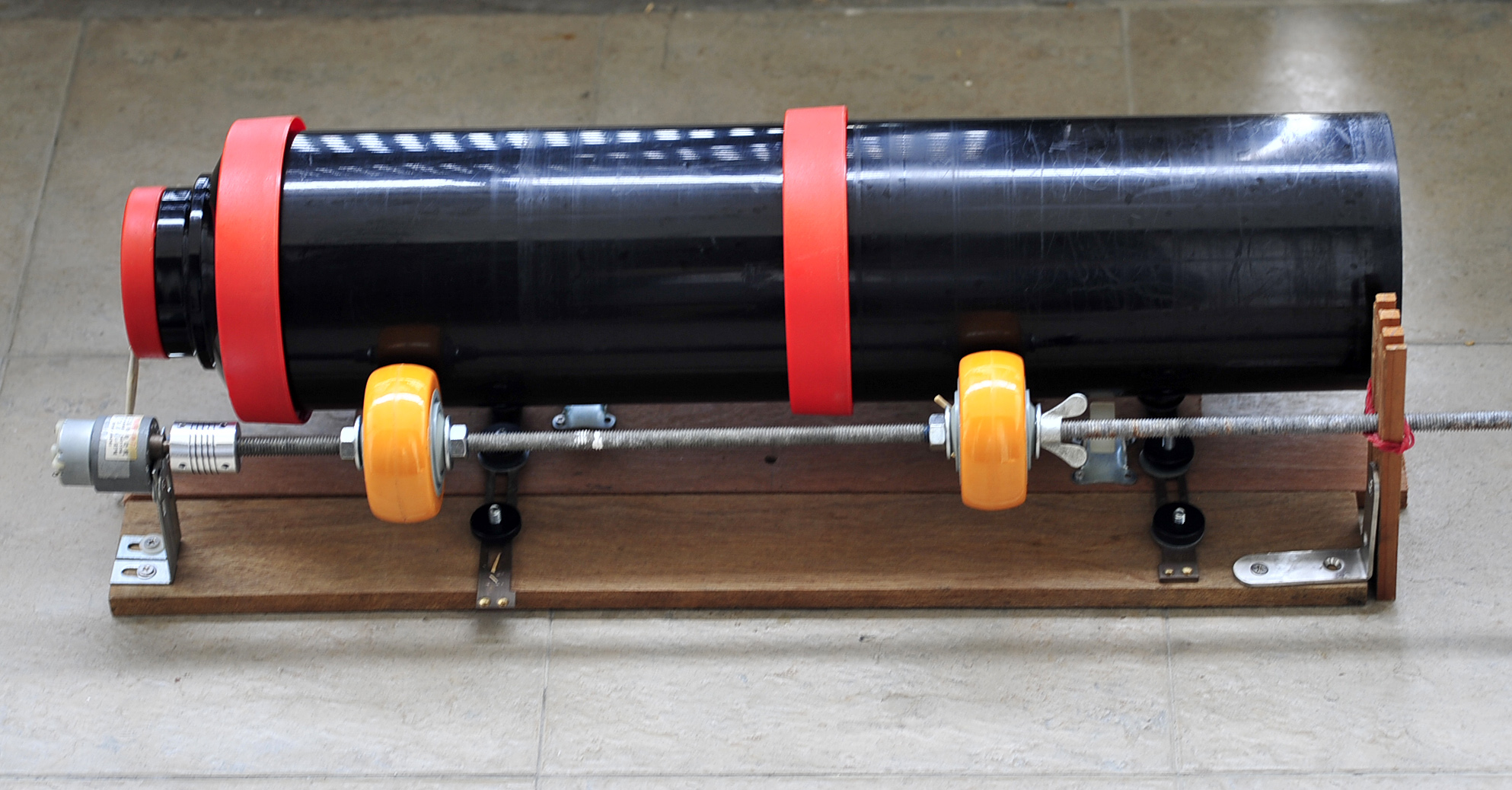
In my previous post about the DIY Rotary Film Processor that I use to process my 8×20 film for my 8×20 camera, I did not go into details about the Arduino code that controls the rotation and timings. This post will explain more about the Arduino portion.
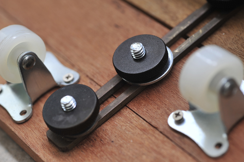
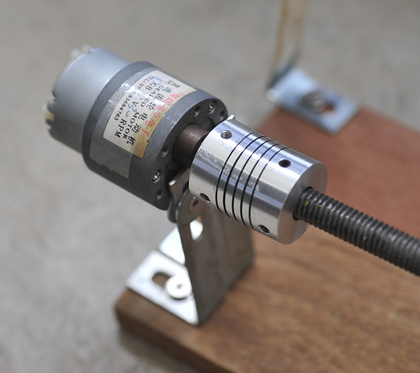
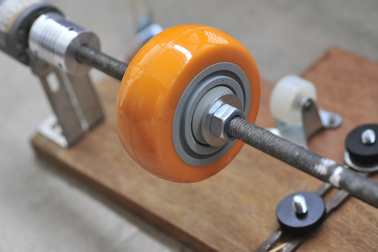
Hardware
I use 3 pieces of boards for the project :
- Arduino UNO
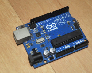
Arduino UNO board
- An motor shield
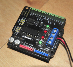
Motor Shield
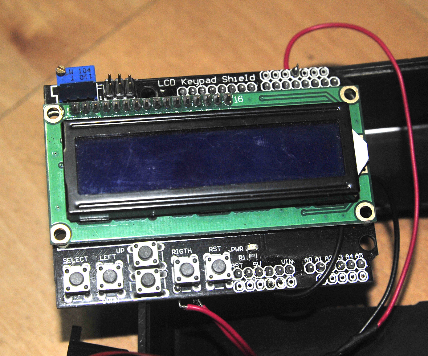
- An LCD shield
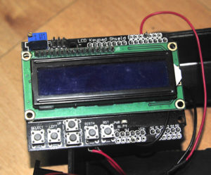
LCD Shield
I am not a programmer so what I did was to piece the different sample codes for the different shields in order to achieve what I need.
This is a Rotary Film Processing controller . It simply rotates a motor for 4.5 seconds in one direction before rotating back in the reverse direction for another 4.5 seconds and stop for a sec. This is considered as one cycle. Therefore 6 cycles of it will constitute 1 min.
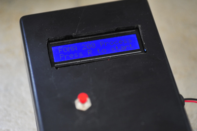
When it is powers on, you will need to press a button (connect to the RIGHT button of the LCD shield) to start the development process. When the first step (ed Prewash for 3 mins) is completed , the buzzer will sound off and you will need to press the same button to continue to the next cycle (of course after pouring out the first and in the next chemical)
Currently, it is coded for my FOMA 200 developing needs. You will probably need to modify the code to your needs.
/* Rotary  Film Processing
 * ------------------
 * This is a Rotary Film Processing controller . It simply rotates a motor for 4.5 seconds in one direction before rotating back in the reverse direction for another 4.5 seconds and stop for a sec
 * . This is considered as one cycle. Therefore 6 cycles of it will constitute 1 min.

 // include the library code:
#include <LiquidCrystal.h>

// initialize the library with the numbers of the interface pins
LiquidCrystal lcd(8, 9, 4, 5, 6, 7);

// define some values used by the panel and buttons
int lcd_key     = 0;
int adc_key_in  = 0;
#define btnRIGHT  0
#define btnUP     1
#define btnDOWN   2
#define btnLEFT   3
#define btnSELECT 4
#define btnNONE   5

int buttonPin=2;
int buttonState=0;
int buttonCount=0;
int EN1 = 6;
int EN2 = 5;  //Roboduino Motor shield uses Pin 9
int IN1 = 7;
int IN2 = 4; //Latest version use pin 4 instead of pin 8
int BUZZ=3;

void Motor2(int pwm, boolean reverse)
        {
          analogWrite(EN1,pwm); //set pwm control, 0 for stop, and 255 for maximum speed
         if(reverse)
         {
          digitalWrite(IN1,HIGH);
         }
        else
        {
          digitalWrite(IN1,LOW);
         }
        }

void Motorprocess(int stepno, int noMins)
{
   int counter;
   int noRepeats;
   noRepeats=noMins * 6;  //6 cycles is one minute, so to repeat for the required no of minutes

     for(counter=0;counter<noRepeats;counter++)
                      { Motor2(255,true);
                       delay(4500); //turn for 4.5secs

                        Motor2(255,false);
                        delay(4500); //reverse and turn for another 4.5 secs
                        Motor2(0,false); //stop for 1 secs
                        delay(1000);
                      }
lcd.setCursor(0,1);
lcd.print("Step ");  //write to LCD that the step is completed
lcd.print(stepno);
         lcd.print(" Done");
          Motor2(0,false);
      digitalWrite(BUZZ, HIGH); //sound the buzzer for a second
       delay(1000);
       digitalWrite(BUZZ, LOW);


 }

// read the buttons
int read_LCD_buttons()
{
 adc_key_in = analogRead(0);      // read the value from the sensor
 // my buttons when read are centered at these valies: 0, 144, 329, 504, 741
 // we add approx 50 to those values and check to see if we are close
 if (adc_key_in > 1000) return btnNONE; // We make this the 1st option for speed reasons since it will be the most likely result
 // For V1.1 us this threshold
 if (adc_key_in < 50)   return btnRIGHT;
 if (adc_key_in < 250)  return btnUP;
 if (adc_key_in < 450)  return btnDOWN;
 if (adc_key_in < 650)  return btnLEFT;
 if (adc_key_in < 850)  return btnSELECT;


 return btnNONE;  // when all others fail, return this...
}

int val = 0;     // variable for reading the pin status

void setup() {

  pinMode(BUZZ,OUTPUT);

  int i;
   for(i=4;i<=7;i++)  //For Arduino Motor Shield
    pinMode(i, OUTPUT);  //set pin 4,5,6,7 to output mode

    analogWrite (10, 10);
     lcd.begin(16, 2);
  // Print a message to the LCD.
  lcd.print("FOMA 200 Process ");
  lcd.setCursor(0, 1);
  lcd.print("Press R to start");
}

void loop(){
  Motor2(0,false);
  int counter;
// buttonState= digitalRead(buttonPin);
buttonState = read_LCD_buttons();  // read the buttons
  if (buttonState==btnRIGHT)//change here
{buttonCount = buttonCount+1;


//if (newState==0 && buttoncount>0)
  switch(buttonCount)
  {

  case  1 : //prewash 3 mins
  lcd.clear();
   lcd.print("1. Prewash ");
      Motorprocess(1, 3);

      break;
  case 2 : //develop 7mins
  lcd.clear();
   lcd.print("2. Develop ");
      Motorprocess(2, 7);

  break;

   case 3 : //Stop Bath 1 Min
     lcd.clear();
   lcd.print("3. Stop Bath ");
     Motorprocess(3, 1);

  break;

   case 4 : // fixer 4 min
        lcd.clear();
   lcd.print("4. Fixer ");
     Motorprocess(4, 4);

  break;

    case 5 : //Wash 1 min
            lcd.clear();
   lcd.print("5. Wash ");
     Motorprocess(5, 2);

  break;


  default :
  buttonCount=0;
  }//end for switch
}
}